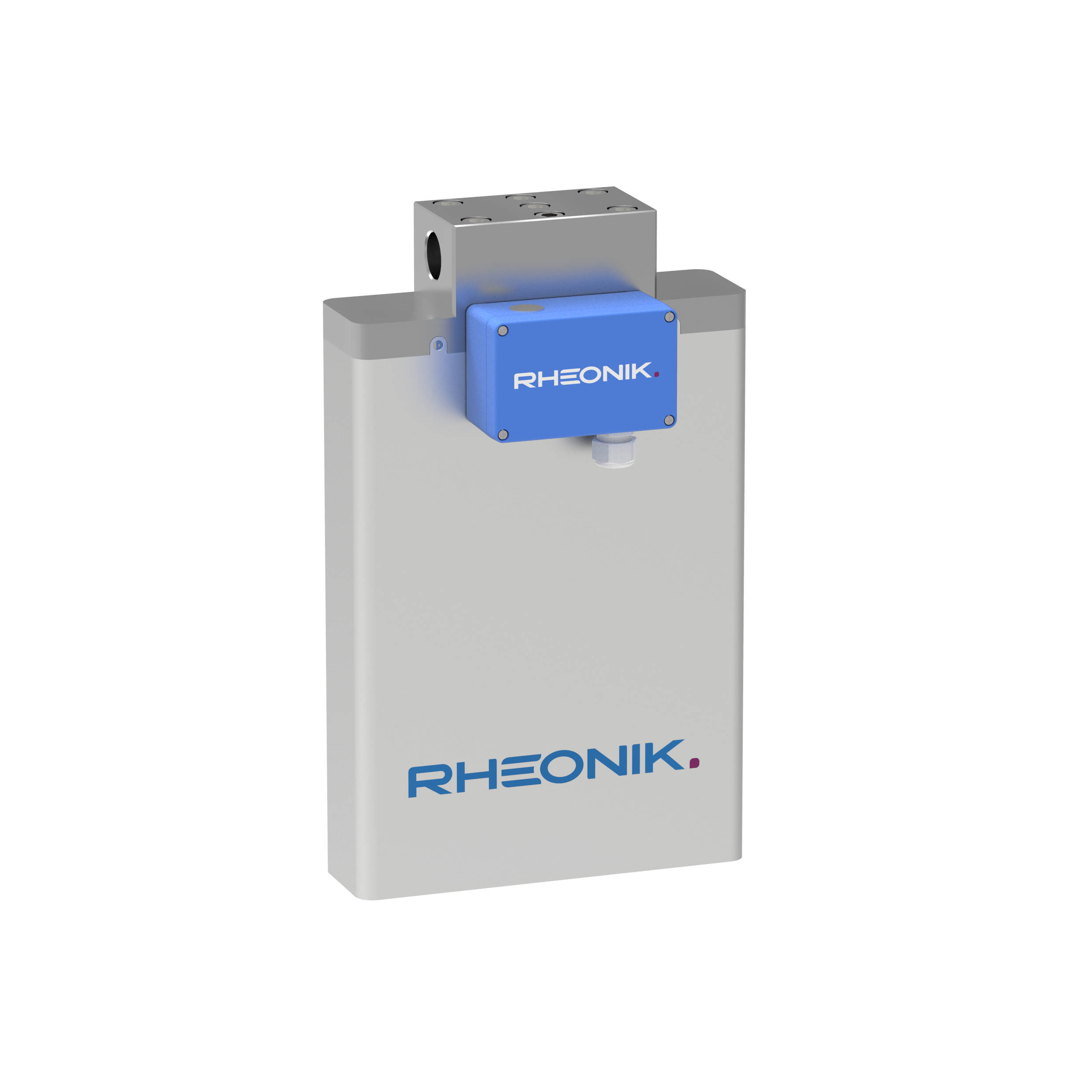
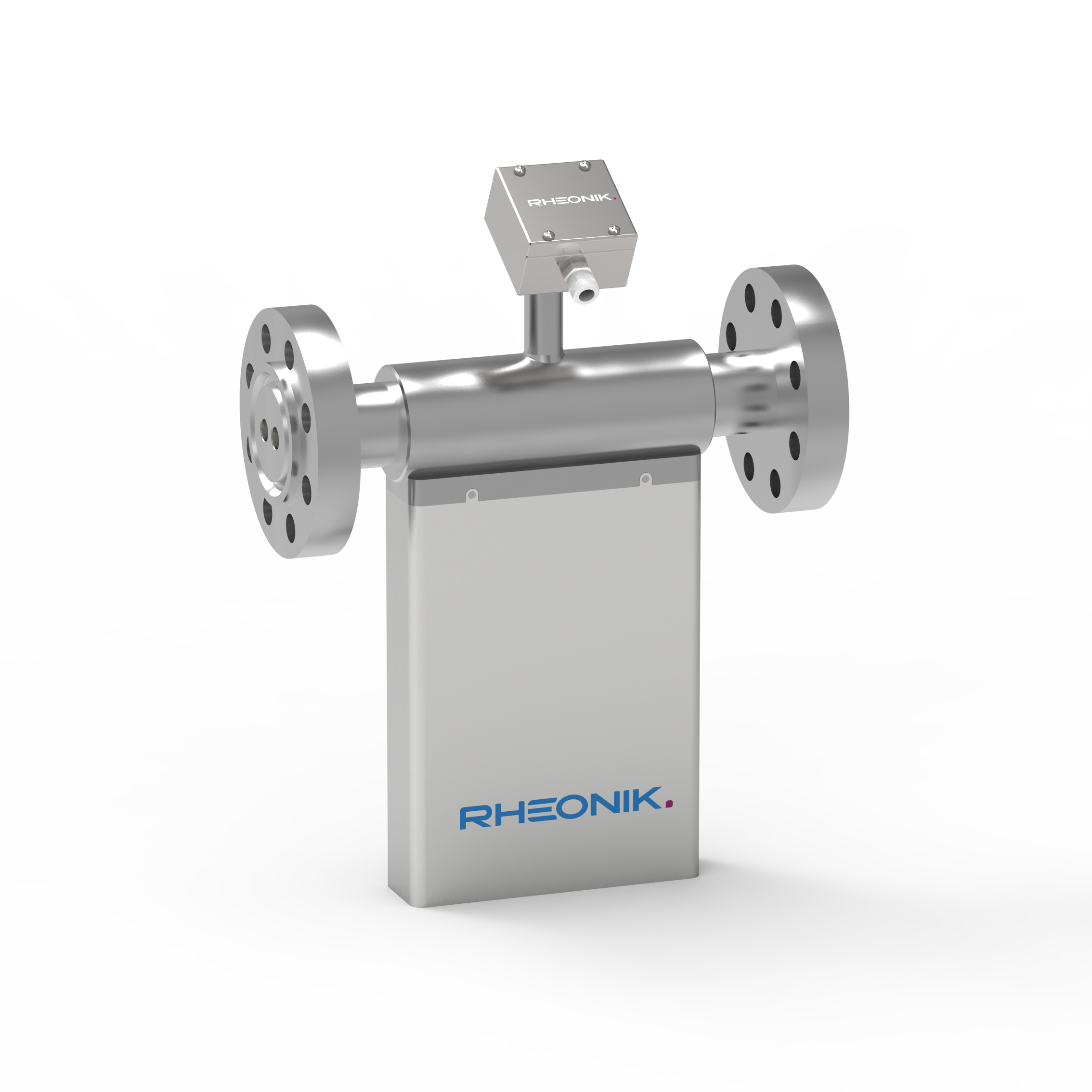
RHM 20

FLOW SENSOR

The RHM 20 is a 2″ meter designed for general purpose flow measurement without the need for maintenance. Robust and accurate, the RHM 20 outperforms other flow technologies at an attractively low cost of ownership.

  • Range: 1 kg/min up to 480 kg/min
  • Pressure: up to 400 bar (5801 psi)
  • Temperature: -50°C (-58°F) up to +210°C (410°F)
  • Accuracy: 0.1 % of rate
  • Materials: SS 316L / SS 316Ti, Alloy C22 – 2.4602, Tantalum – UNS R05200, Super Duplex – 1.4410
  • Process Connection: 1" up to "
CONFIGURE
CATEGORY Medium Size Sensors, Chemical Injection, Fuel Consumption, Oil Measurement, Plastics Production

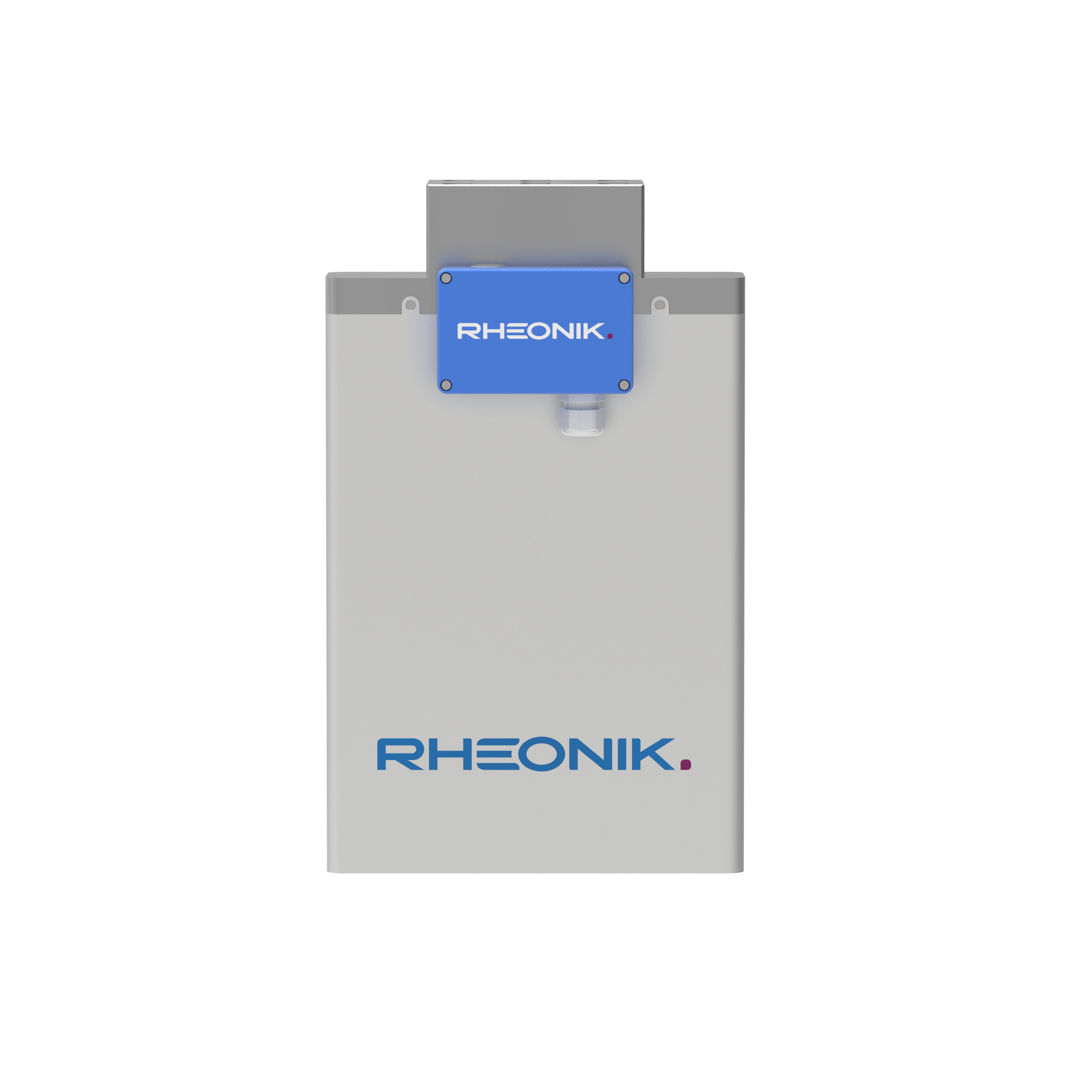
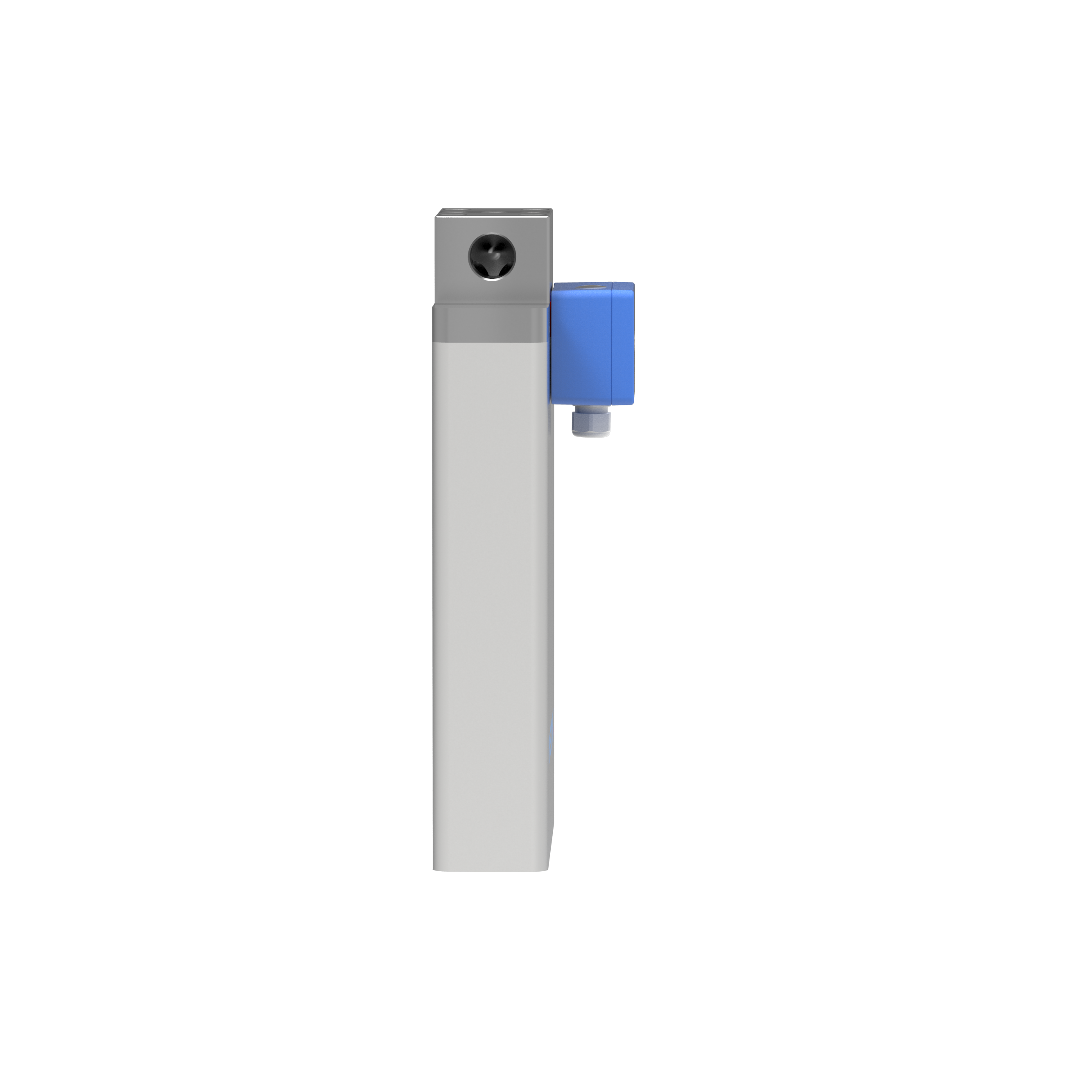
Face to Face dimension

Manifold design with thread connections
parallel tube / dual path

Process Connection

Face to Face (L)

Female Thread G 1”

136 mm / 5.35 in

Female Thread 1” NPT

136 mm / 5.35 in


Dimension

mm / in

A1

285 mm / 11.22 in

A2

300 mm / 11.81 in

B1

50 mm / 1.97 in

B2

70 mm / 2.76 in

H1

454 mm / 17.87 in

H2

486 mm / 19.11 in

W

See datasheet


Manifold design with thread connections
serial tube / single path

Process Connection

Face to Face (L)

Female Thread G 1”

136 mm / 5.35 in

Female Thread 1” NPT

136 mm / 5.35 in


Dimension

mm / in

A1

285 mm / 11.22 in

A2

300 mm / 11.81 in

B1

50 mm / 1.97 in

B2

70 mm / 2.76 in

H1

454 mm / 17.87 in

H2

486 mm / 19.11 in

W

See datasheet


Manifold design with flange connections
parallel tube / dual path

Process Connection

Face to Face (L)

ANSI 1½" 150#RF

460 mm / 18.11 in

ANSI 1½" 300#RF

460 mm / 18.11 in

ANSI 1½" 600#RF

500 mm / 19.69 in

DIN DN40/PN40 Form B1

460 mm / 18.11 in

DIN DN40/PN100 Form B2

500 mm / 19.69 in


Dimension

mm / in

A1

285 mm / 11.22 in

A2

300 mm / 11.81 in

B1

50 mm / 1.97 in

B2

70 mm / 2.76 in

H1

454 mm / 17.87 in

H2

486 mm / 19.11 in

W

See datasheet


Manifold design with flange connections
serial tube / single path

Process Connection

Face to Face (L)

ANSI 1½" 150#RF

460 mm / 18.11 in

ANSI 1½" 300#RF

460 mm / 18.11 in

ANSI 1½" 600#RF

500 mm / 19.69 in

DIN DN40/PN40 Form B1

460 mm / 18.11 in

DIN DN40/PN100 Form B2

500 mm / 19.69 in


Dimension

mm / in

A1

285 mm / 11.22 in

A2

300 mm / 11.81 in

B1

50 mm / 1.97 in

B2

70 mm / 2.76 in

H1

454 mm / 17.87 in

H2

486 mm / 19.11 in

W

See datasheet


Sealless design with flange connections
parallel / dual path

Process Connection

Face to Face (L)

ANSI 2" 150#RF

460 mm / 18.11 in

ANSI 2" 300#RF

460 mm / 18.11 in

ANSI 2" 600#RF

500 mm / 19.69 in

ANSI 2" 1500#RF

500 mm / 19.69 in

ANSI 2" 1500#RTJ

500 mm / 19.69 in

DIN DN50/PN40 Form B1

460 mm / 18.11 in

DIN DN50/PN100 Form B2

500 mm / 19.69 in

Grayloc Hub 2½" GR20

400 mm / 15.75 in


Dimension

mm / in

A1

285 mm / 11.22 in

A2

300 mm / 11.81 in

B1

50 mm / 1.97 in

B2

70 mm / 2.76 in

H1

454 mm / 17.87 in

H2

540 mm / 21.26 in

W

See datasheet


Sealless design with flange connections
parallel / dual path

Process Connection

Face to Face (L)

ANSI 2" 150#RF

460 mm / 18.11 in

ANSI 2" 300#RF

460 mm / 18.11 in

ANSI 2" 600#RF

500 mm / 19.69 in

ANSI 2" 1500#RF

500 mm / 19.69 in

ANSI 2" 1500#RTJ

500 mm / 19.69 in

DIN DN50/PN40 Form B1

460 mm / 18.11 in

DIN DN50/PN100 Form B2

500 mm / 19.69 in

Grayloc Hub 2½" GR20

400 mm / 15.75 in

Sanitary 1" Triclamp, DIN 32676

350 mm / 13.78 in

Sanitary NW20, DIN 11851

350 mm / 13.78 in


Dimension

mm / in

A1

285 mm / 11.22 in

A2

300 mm / 11.81 in

B1

50 mm / 1.97 in

B2

70 mm / 2.76 in

H1

454 mm / 17.87 in

H2

540 mm / 21.26 in

W

See datasheet


Sealless design with threaded connections
parallel / dual path

Process Connection

Face to Face (L)

Female Thread G ¾”

400 mm / 15.75 in

Female Thread ¾” NPT

400 mm / 15.75 in

Swagelok 1" tube compression fitting
(SS-1610-1-16W)

560 mm / 22.05 in

Dimension

mm / in

A1

285 mm / 11.22 in

A2

300 mm / 11.81 in

B1

50 mm / 1.97 in

B2

70 mm / 2.76 in

H1

454 mm / 17.87 in

H2

540 mm / 21.26 in

W

See datasheet


Common Dimensions for all Construction Types

  • Standard blue aluminum terminal box, size = 125 x 80 x 57 mm (4.92 x 3.15 x 2.24 in)

  • Terminal boxes are supplied with an M20 x 1.5 cable entry and a polyamide compression cable gland fitting (for cable diameters 7 - 14 mm / 0.28 - 0.56 in). M25 x 1.5, 1⁄2” NPT, 3⁄4” NPT cable entries (without gland) are optionally available and must be ordered separately

  • Optionally available: SS 316 box, size = 100 x 100 x 61 mm (3.94 x 3.94 x 2.40 in) – only with remote transmitter


For more information and dimensions see datasheet under downloads.