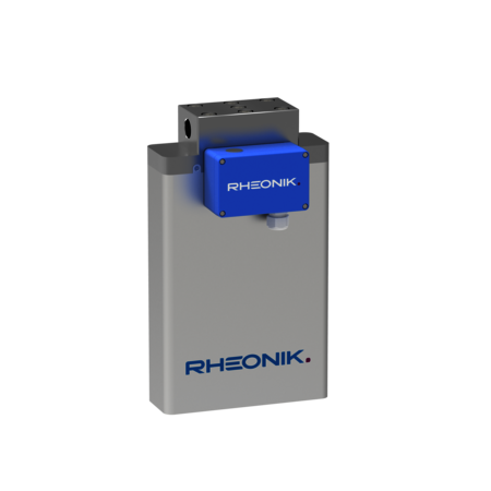


RHM 15
FLOW SENSOR
The RHM 15 is an all-purpose meter suitable for liquid processing plants. A wide application flow range capability allows for commonality of installation across numerous lines – a real benefit to owners and operators.
- Range: 0.5 kg/min up to 240 kg/min
- Pressure: up to 1282 bar (18593 psi)
- Temperature: -196°C (-321°F) up to +350°C (662°F)
- Accuracy: 0.1 % of rate
- Materials: SS 316L / SS 316Ti, Alloy C22 – 2.4602, Super Duplex – 1.4410, Tantalum – UNS R05200
- Process Connection: ¾" up to 2 ½"
All dimensions apply to standard designs. Face-to-face length L tolerance: ±2 mm. Customized lengths and process connections not listed here are available on request (see datasheet).
Dimensions and Face-to-Face Lengths
Connection block design with threaded connections
Parallel tube / dual path

Process Connection | Face to Face (L) |
|---|---|
Female Thread G ¾″ | 140 mm / 5.51 in |
Female Thread ¾″ NPT | 140 mm / 5.51 in |
Autoclave ¾″ MP – ¾″–14 NPSM | 140 mm / 5.51 in |
Dimension | mm / in |
|---|---|
A | 230 mm / 9.06 in |
B | 79 mm / 3.11 in |
H1 | 395 mm / 15.55 in |
H2 | 372 mm / 14.65 in |
H3 | 345 mm / 13.58 in |
W | See datasheet |
Connection block design with flange connections
Parallel tube / dual path

Process Connection | Face to Face (L) |
|---|---|
ANSI 1″ 150# RF/SF | 400 mm / 15.75 in |
ANSI 1″ 300# RF/SF | 400 mm / 15.75 in |
ANSI 1″ 600# RF/SF | 400 mm / 15.75 in |
ANSI 1″ 1500# RF/SF | 450 mm / 17.72 in |
ANSI 1″ 1500# RTJ | 450 mm / 17.72 in |
DIN DN25/PN40 Form B1 | 400 mm / 15.75 in |
DIN DN25/PN100 Form B2 | 400 mm / 15.75 in |
JIS B 2220 RF 10k 25A (1″) | 400 mm / 15.75 in |
JIS B 2220 RF 20k 25A (1″) | 400 mm / 15.75 in |
Dimension | mm / in |
|---|---|
A | 230 mm / 9.06 in |
B | 79 mm / 3.11 in |
H1 | 395 mm / 15.55 in |
H2 | 372 mm / 14.65 in |
W | See datasheet |
Sealless design with flange/hub and threaded connections
Parallel tube / dual path – cryogenic or high temperature applications

Process Connection | Face to Face (L) |
|---|---|
Female Thread G ¾″ | 400 mm / 15.75 in |
Female Thread ¾″ NPT | 400 mm / 15.75 in |
ANSI 1½″ 150# RF | 400 mm / 15.75 in |
ANSI 1½″ 300# RF | 400 mm / 15.75 in |
ANSI 1½″ 600# RF | 400 mm / 15.75 in |
ANSI 1½″ 1500# RF | 400 mm / 15.75 in |
ANSI 1½″ 2500# RF | 450 mm / 17.72 in |
ANSI 1½″ 1500# RTJ | 400 mm / 15.75 in |
ANSI 1½″ 2500# RTJ | 450 mm / 17.72 in |
DIN DN40/PN40 Form B1 | 400 mm / 15.75 in |
DIN DN40/PN100 Form B2 | 400 mm / 15.75 in |
G-LOK® Hub 2″ GR14 | 420 mm / 16.54 in |
G-LOK® Hub 2½″–3″ GR20 | 450 mm / 17.72 in |
Dimension | mm / in |
|---|---|
A | 230 mm / 9.06 in |
B | 79 mm / 3.11 in |
H1 | 438 mm / 17.24 in |
H2 | 387 mm / 15.24 in |
W | 100 mm / 3.94 in |
For cryogenic or high temperature applications. Dimensions shown apply to the arrangement in the drawing (see datasheet).
Sealless design with flange/hub connections
Parallel tube / dual path – other temperature ranges (see datasheet)
Process Connection | Face to Face (L) |
|---|---|
ANSI 1½″ 150# RF | 400 mm / 15.75 in |
ANSI 1½″ 300# RF | 400 mm / 15.75 in |
ANSI 1½″ 600# RF | 400 mm / 15.75 in |
ANSI 1½″ 1500# RF | 400 mm / 15.75 in |
ANSI 1½″ 2500# RF | 450 mm / 17.72 in |
ANSI 1½″ 1500# RTJ | 400 mm / 15.75 in |
ANSI 1½″ 2500# RTJ | 450 mm / 17.72 in |
DIN DN40/PN40 Form B1 | 400 mm / 15.75 in |
DIN DN40/PN100 Form B2 | 400 mm / 15.75 in |
G-LOK® Hub 2″ GR14 | 420 mm / 16.54 in |
G-LOK® Hub 2½″–3″ GR20 | 450 mm / 17.72 in |
Dimensional drawing and installation variants (see datasheet).
Dimension | mm / in |
|---|---|
A | 230 mm / 9.06 in |
B | 79 mm / 3.11 in |
H2 | 387 mm / 15.24 in |
Dimensions above the process connection depend on the terminal box or integral transmitter. Refer to the corresponding drawing (see datasheet).
Connection / Transmitter | B1 | B2 | H1 |
|---|---|---|---|
Remote transmitter, aluminum terminal box | 11 mm / 0.43 in | 100 mm / 3.94 in | 227 mm / 8.94 in |
Integral RHE 45 | 11 mm / 0.43 in | 85 mm / 3.35 in | 227 mm / 8.94 in |
Integral RHE 42 | 55 mm / 2.17 in | 88 mm / 3.46 in | 252 mm / 9.92 in |
Remote transmitter, stainless steel terminal box | 13 mm / 0.51 in | 113 mm / 4.45 in | 222 mm / 8.74 in |
For other integral transmitter configurations, consult the corresponding transmitter datasheet. H1 and H2 refer to the separate dimensions shown in the drawing.
Sealless design with threaded connections
Parallel tube / dual path – other temperature ranges (see datasheet)
Process Connection | Face to Face (L) |
|---|---|
Female Thread G ¾″ | 400 mm / 15.75 in |
Female Thread ¾″ NPT | 400 mm / 15.75 in |
Dimensional drawing and installation variants (see datasheet).
Dimension | mm / in |
|---|---|
A | 230 mm / 9.06 in |
B | 79 mm / 3.11 in |
H2 | 387 mm / 15.24 in |
Dimensions above the process connection depend on the terminal box or integral transmitter. Refer to the corresponding drawing (see datasheet).
Connection / Transmitter | B1 | B2 | H1 |
|---|---|---|---|
Remote transmitter, aluminum terminal box | 11 mm / 0.43 in | 100 mm / 3.94 in | 227 mm / 8.94 in |
Integral RHE 45 | 11 mm / 0.43 in | 85 mm / 3.35 in | 227 mm / 8.94 in |
Integral RHE 42 | 55 mm / 2.17 in | 88 mm / 3.46 in | 252 mm / 9.92 in |
Remote transmitter, stainless steel terminal box | 13 mm / 0.51 in | 113 mm / 4.45 in | 222 mm / 8.74 in |
For other integral transmitter configurations, consult the corresponding transmitter datasheet. H1 and H2 refer to the separate dimensions shown in the drawing.
Common Dimensions for Terminal Boxes
• Standard coated aluminum terminal box: 125 × 80 × 57 mm (4.92 × 3.15 × 2.24 in).
• Optional stainless steel terminal box: 100 × 100 × 61 mm (3.94 × 3.94 × 2.40 in), for connection to a remote transmitter.
• Terminal boxes are supplied with an M20 × 1.5 cable entry. Other optional entries are available (see datasheet).
Terminal box offset and integral transmitter dimensions depend on the sensor temperature range and connection arrangement (see datasheet).
